RFID Sensors for Smart Store
The viewneo RFID Sensor System
RFID (Radio-Frequency Identification) is a technology for contactless identification of objects with radio waves.
 The viewneo RFID Sensor System consists of
- RFID Reader
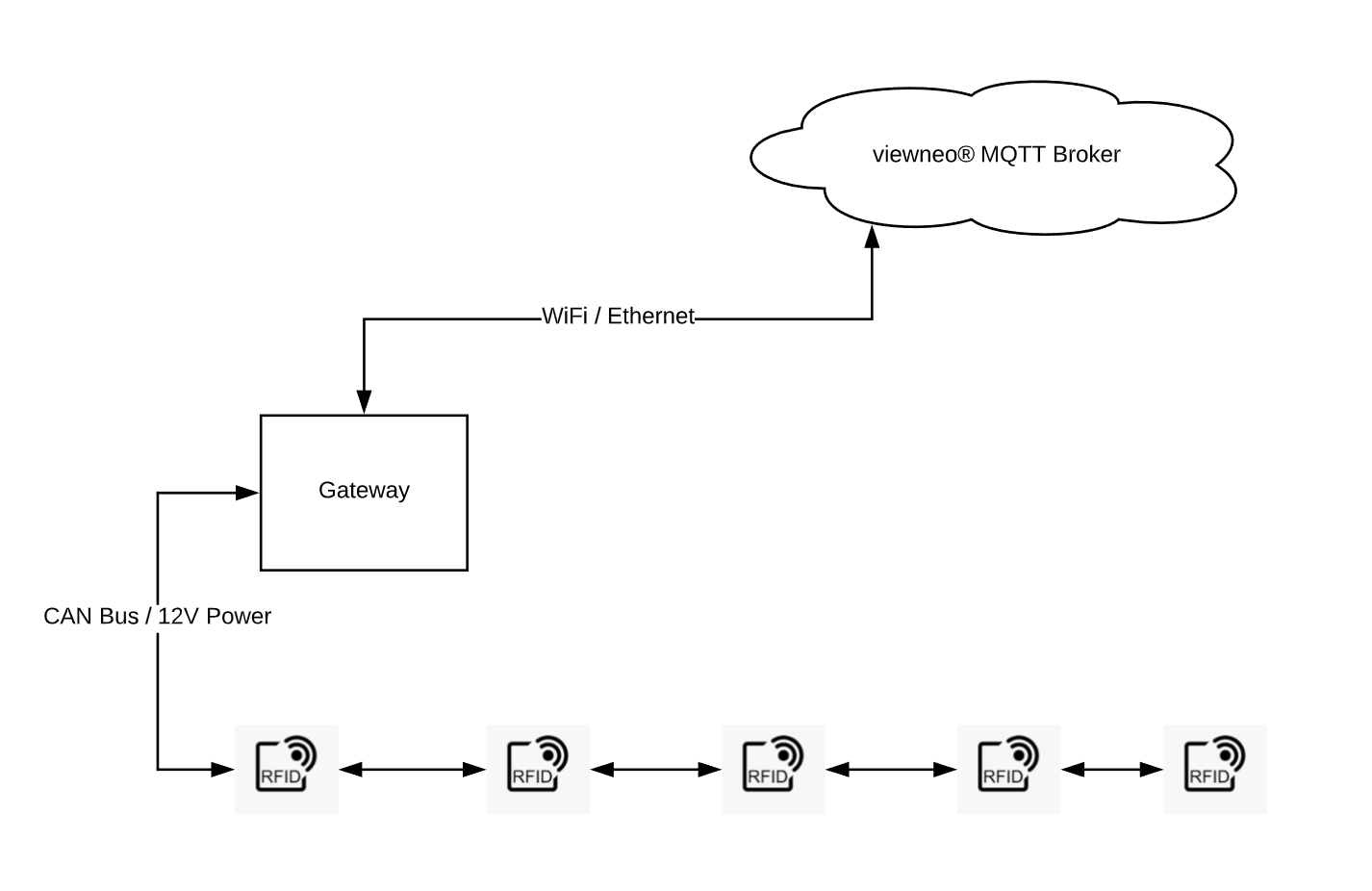
- RFID Gateway
The RFID Sensor System is used to create interactive product shows (Lift & Learn) in stationary retail. Thereby products are provided with a RFID sticker. These stickers are special stickers that carry an RFID chip inside.
As soon as a customer either places a product on a sensor or removes a product from the sensor, the viewneo Event Management can react to it.
An example application, shown at Euroshop 2020 in Düsseldorf:
Structure
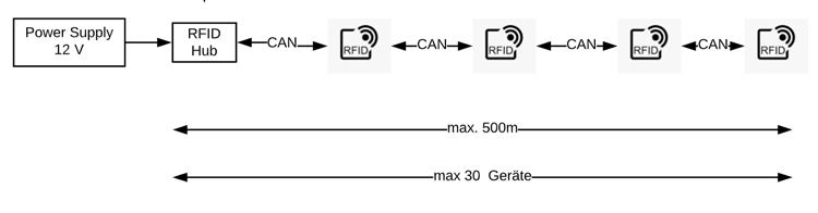
Up to 30 viewneo RFID readers (per gateway / hub) can be connected in series. When a RFID tag is placed on a reader or a placed tag is removed from the reader, the transmitter sends the tag ID to the RFID gateway.
Communication via CAN bus
Communication between the readers and the gateway takes place via a CAN bus line. The maximum length of the CAN bus is 500 meters. So this is the distance between the first element in the bus - e.g. the gateway - and the last element (last reader).
Termination of the first and last device in the CAN bus
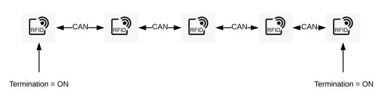
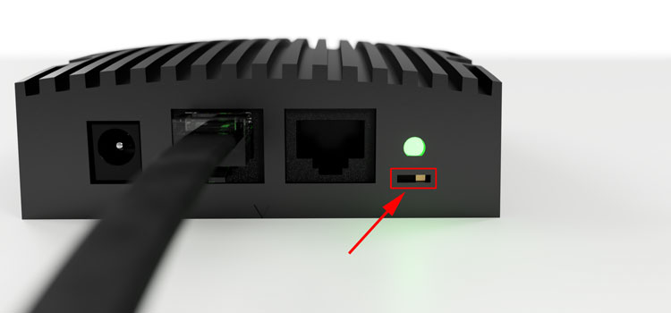
**The first and the last device in the CAN bus must be terminated. To do this, the switch on the front right side must be pushed in the direction "ON". All other devices must have the switch position "OFF", otherwise the communication in the bus system does not work properly.
Power supply
CAN bus and power supply are wired via standard Ethernet LAN cable (CAT 5 or higher). A 12V power supply only needs to be connected to one of the devices.
**The power supply of all other devices is done via the Ethernet cables between the devices in the CAN bus. So a power supply can be connected either to a RFID Reader or to the RFID Gateway for power supply.
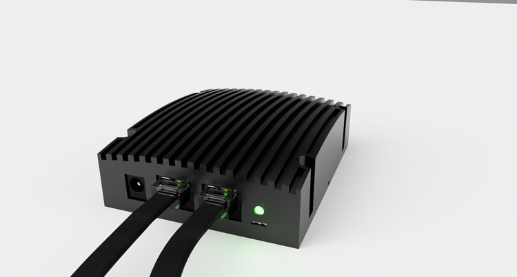 In the picture above: A Reader in CAN Bus (in/out) without power supply connected, receiving power from the CAN Bus line (Ethernet cable). The LED indicates that the reader is powered. If the device is not at the beginning or end of the CAN bus, then 2 CAT cables are connected for CAN-IN and CAN-OUT. It does not matter which of the two connections is used for CAN-IN or CAN-OUT.
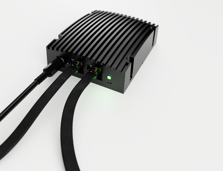 In the picture above: A reader in the CAN bus with connected power supply.
Connecting the network cable
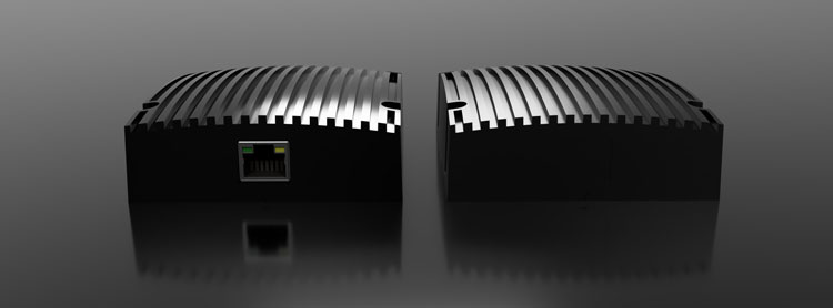
On the back of the gateway there is another Ethernet socket, which is used for the network connection to the Internet.
**CARE! Do not interchange network cable and CAN bus line.
Since the network line and CAN bus both use a CAT cable, it is easy to get these cables mixed up. Always use a colored cable for the Internet line for better differentiation.
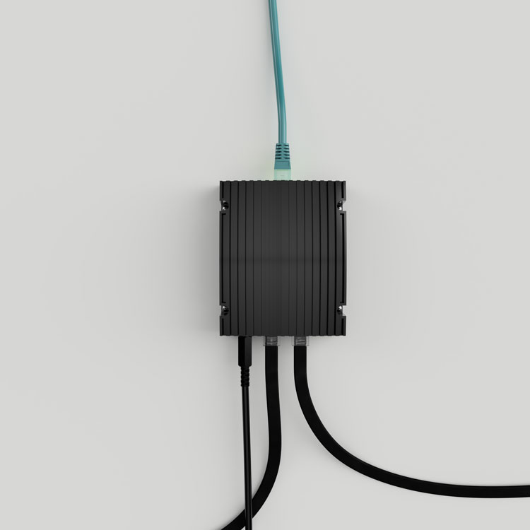 Pictured above: A RFID gateway, wired with power supply and CAN bus in/out (bottom) and network cable (top).
For bus lines over 100 meters, 2 or more power supplies can be used. However, only power supplies of the same type and power / supply voltage may be used. The power supply units should then be distributed as evenly as possible over the length of the bus line.
Technical data
| Min | Max | ||
|---|---|---|---|
| Number of readers | 1 | 30 | |
| Number of gateways | 1 | 1 | |
| Length CAN Bus | 1m | 500m | |
| Bandwidth | 125kb/s | 1mbit/s | |
| power supply | 12V | 24V | Translated with www.DeepL.com/Translator (free version) |